This lab consists in Automatically Dimming an LED according with ambient light. Besides involving an interesting analog transducer, the Photoresistor, this exercise also approaches Pulse Width Modulation (PWM), a technique widely used to control the power supplied to electrical devices, especially to inertial loads such as motors.
In summary, PWM is a modulation technique that consists in dynamically varying the duration (width) of an electrical pulse based on a digital signal. The switching of the output signal between on and off must be fast enough so the circuit being controlled perceives it as a waveform (and not as consecutive stop-and-go signals). Respected the switching rate, PWM acts on the controlled circuit varying the voltage (and current) proportionally to the time the signal is kept on (called duty cycle).
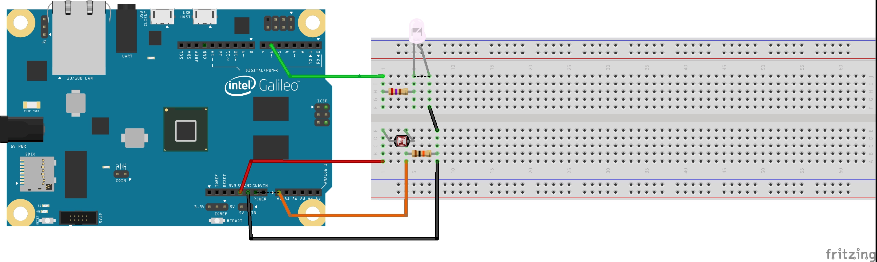
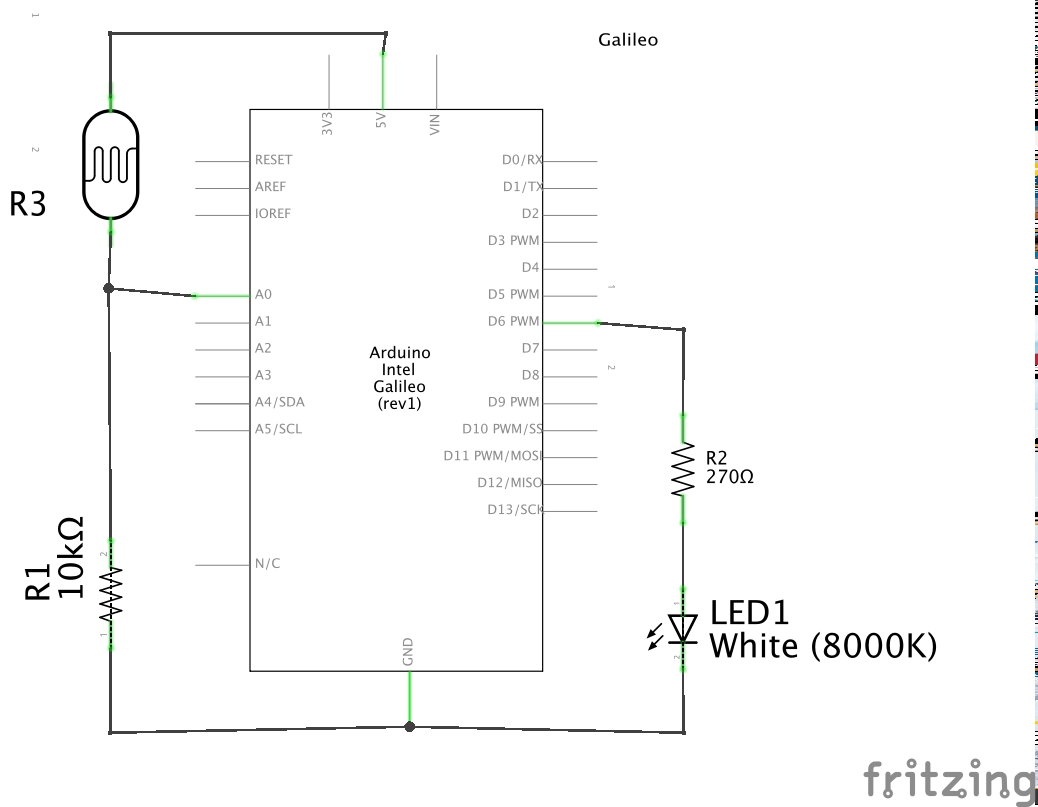
For this lab, a switching frequency a bit above 100 Hz will do. The photoresistor (or LDR) will be connected to the an ADC channel, so the microcontroller can asses the ambient light.
Let's begin with a pseudo code (actual coding is up to you):
1. |
int main() { |
The pseudo-code is self-explaining: an infinite loop reading the ADC channel to which the photoresitor has been connected, a scaling from the read value to yield the PWM duty cycle and a delay to avoid overshooting.
For this lab, you'll need the following components: