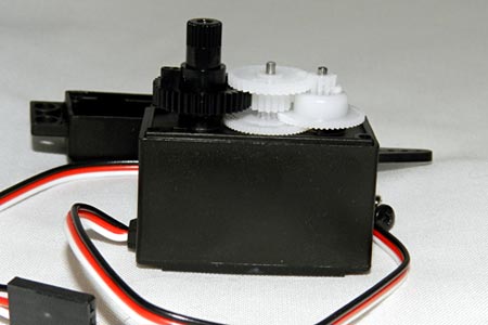
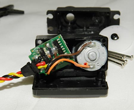
Introduction: A Servo Motor is a type of DC motor that, via PWM (Pulse-Width Modulation), rotates with very high precision. An electronic control board connected to a sensor tracks the gears inside the Servo enclosure, decoding the rotations of these gears in a way that makes possible to the user control how much the servo shaft will move.
→ One Servo Motor;
→ One 10k Ohm Linear Potentiometer;
→ Protoboard;
→ Jumpers.
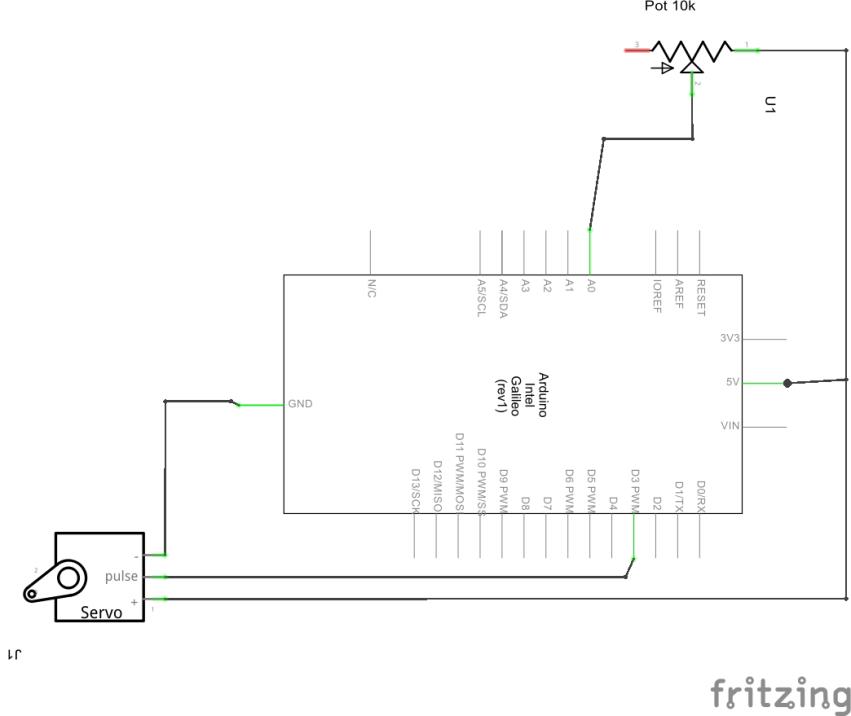
On a Protoboard, assemble the circuit below:
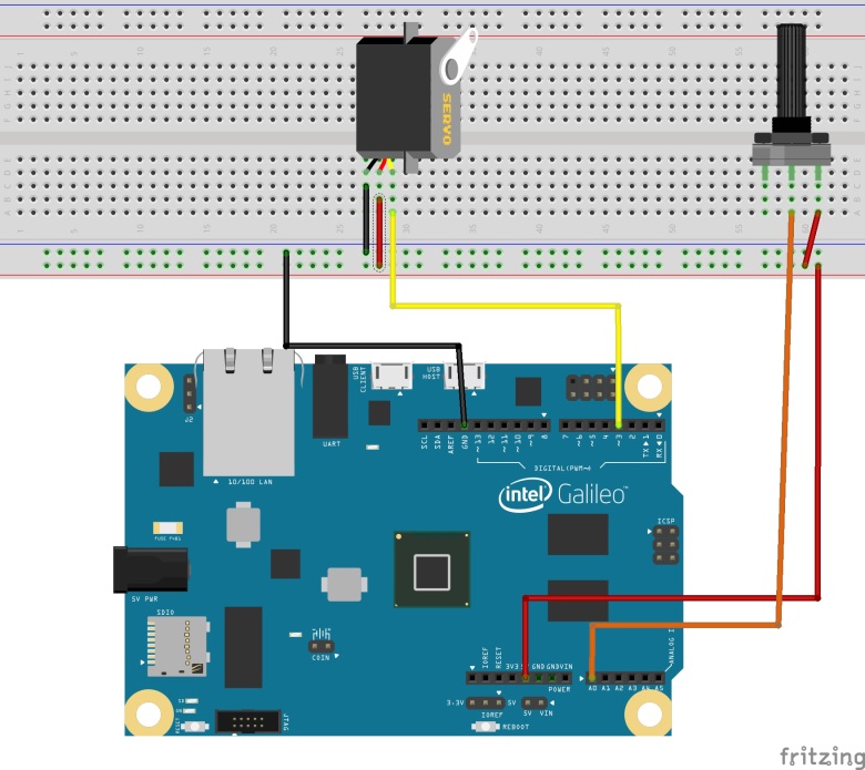
Where:
→ Red wires and black wires referes to VCC 5V and GND, respectively;
→ The Yellow wire are the PWM Servo signal;
→ The Orange Wire leads the voltage through the potentiometer resistance to be read by ADC 0.
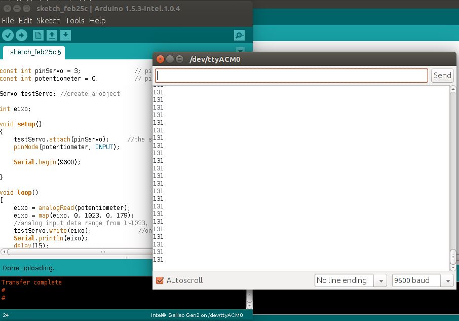
Upload the following code to Galileo, using the Arduino IDE or compiling directly from Linux terminal:
1. |
include "Servo.h" |
With the code running on Galileo, open “Serial Monitor” and turn the potentiometer to both sides.